Carbon fiber composites currently offer the best weight, stiffness, durability and ease of use parameters out of all other materials available for bicycle component manufacture. Composite literally means made of several materials – in this case carbon fibers, and resin.
Carbon fiber layup and the quality of manufacture is extremely important in being able to control the torsional loads. Unlike isotropic materials (Read more about isotropy here: Isotropy), carbon fiber composites are a man made material that can be made to satisfy virtually any mechanical property without changing the overall structural shape of the part, they are entirely anisotropic.
This means that in order to achieve optimal stiffness at any part of the frame, once the basic shape requirements are met, all that is needed is to improve the carbon fiber layup and the manufacturing process used. There is no need to make structural changes. However, making adequate changes to the carbon fiber layup and manufacturing process is very expensive, so you will more often see innovative shapes and mechanical solutions that purport to improve stiffness with a side benefit of achieving lower costs of production. Due to the smaller size of our company, production costs and the resultant increase in inventory costs are not a major concern for us. We can afford to focus on achieving the best results using the best possible materials and proven technologies. (See: Why Buy Velocite?)
Manufacture
Good article on how carbon fiber itself is made: Wikipedia – Carbon (fiber)
For more reading: How products are made – Carbon fiber and Japanese Carbon Fiber Manufacturers Association FAQ
Carbon fiber supply overview
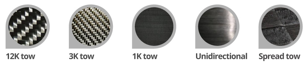
The main suppliers, representing 70% of the total market, of the type of carbon fiber used for the manufacture of bicycle parts are Toho Tenax, Toray Industrial and Mitsubishi Rayon, all based in Japan. They are the main suppliers in what is called normal tow (under 12000 fibers) carbon fiber, or commonly known as 1k, 3k, 12k weave, and UD carbon fiber. Recently another type of carbon fiber fabric became available, spread tow. As the name implies this type of fabric is made by “spreading” the tow, usually a 12k tow, to generate a tape that is much wider than the original 12k tow. The act of spreading the tow results in a more 2-dimensional distribution of fibers, thus the fabric made from the spread tow can cover a larger surface area, than fabrics made from standard tow using the same number of fibers. This leads to spread tow fabrics having a much lower weight than standard fabrics.
It is important to note that sports sector represents only 20% of the total carbon fiber consumption, with bicycle parts manufacture therefore probably representing only 5% of the global consumption of carbon fiber. This means that the carbon fiber materials and associated resins that the bike industry is using were originally developed for another sector such as aerospace. There are no bike specific carbon fiber materials, or resins despite of what some more fanciful marketing materials my claim.
Carbon fiber use in the bicycle industry
Most commonly, the carbon fiber that is used comes in rolls of pre-impregnated fabric, or prepreg. Since carbon fiber composite is a composite material that combines carbon fiber and resin, prepreg means that the carbon fiber has already been saturated with resin. How much resin is present and what type it is depends on the grade and end use of the carbon fiber prepreg.
Bicycle components, specifically bike frames are made using various grades of carbon fiber characterized mainly by their tensile strength and tensile modulus. Tensile strength is the amount of force needed to cause the fibers to break, while the tensile modulus is a measure of the carbon fiber’s stiffness.
The cost of the materials generally go up with the increase in tensile strength, or increase in tensile modulus. The tow (weave) also determines the cost of material with larger tow prepreg (eg. 12k) costing less due to the lower cost of manufacture.
The chart below prepared by Toray Industrial illustrates some basic characteristics of the Toray range of carbon fiber prepreg, and illustrates why using multiple layers of various modulus carbon fiber is the only way to make high performance, safe and durable bike frames.
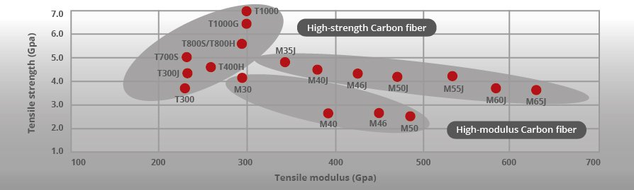
You will note that tensile strength and tensile modulus are almost inversely proportional, that is as the fibers become stronger in tension and resistant to breakage, they become less stiff. In bike frame manufacturing this means that at present it is not possible to construct an exceptionally light frame (below approx . 850g) out of carbon fiber composite that is at the same time stiff and resistant to spontaneous cracking and damage in case of a fall. This is why all Velocite frames use what we term Velocite Optimised Carbon or VOC, which is a short way of saying that our frames use multiple layers of varying modulus carbon fiber in specific areas of each frame size in order to achieve the desired stiffness, weight and durability.
Carbon fiber layup
Carbon fiber prepreg cloths of varying modulus and tow are cut into smaller patches according to the layup chart which varies for each frame model and size. For example, Velocite Geos has four sizes so this means that just for the one model there are 4 unique layup charts – of course closely related to each other, but still not identical.
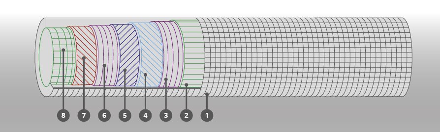
This is an example of an actual engineering layup diagram for the Velocite Geos (with location, carbon fiber grade and orientation (eg. 0 degree, 45 degree, 90 degree) information deleted for confidentiality reasons). There are 8 layers in total using three different types of carbon fiber. Our layup is optimised to handle specific directional loads acting on the frame. This means that, for example, in the down tube, top tube, seat stays and the chain stays, the layup that prioritises handling of torsional forces is used.
The high importance of laying down patches of carbon fiber prepreg in different orientations is due to carbon fiber having maximum strength only along the lengths of the fibers. This also helps illustrate why using uni-directional fiber instead of woven carbon fiber (eg. 1k, 3k, 12k) creates stronger frames. When using woven carbon fiber, at any one time half of the fibers are not oriented so that the force acts along their length. Of course using multiple layers of woven carbon fiber in different orientations would help mitigate this somewhat. However, the other problem with woven fabrics is localized bending of the fibers as the weaves pass across each other. This deficiency affects all woven carbon fibers and cannot be easily overcome.
Thus, the main use of woven carbon fiber when it comes to bicycle frames is for appearance. 1k, 3k, or now more rarely 12k carbon fiber is used on the surface of the frame to give it a more uniform “carbon look”. At Velocite we use unidirectional carbon fiber and only resort to woven carbon fiber when it has clear structural, or mechanical benefits, and never as a cosmetic top layer. When you look at a Velocite frame you can see the intricate structural top carbon fiber layer in full view. For more reading: D. Chung Composite Materials Science and Applications, 2nd Edition
Manufacturing process
Carbon fiber composite frames can be manufactured using the following two methods:
- 1. Resin transfer (RTM), or fillament-winding method – used in lugged construction where pre-formed carbon tubes are bonded to internal, or external lugs (see: lugged frame construction) and are held in place with glue. Commonly the lug material is now also a carbon fiber composite.
- 2. Closed mold using bag, foam core, sacrificial core or polymer mandrel molding – used to make structural elements for tube-to-tube (bonded tube) frames, and to make monocoque frames.
Lugged construction using RTM or fillament-winding carbon tubes
This was the original method of carbon frame manufacture and is a direct descendant of the lugged frame construction used for steel frames. Frames made using the lugged process can offer high performance, but the main reasons for the use of this method to make contemporary frames are: ease of custom geometry changes and lower labour and equipment costs. This allows some high quality modern carbon frame makers to have a successful frame making business outside of Asia.
The tubes themselves are commonly made via an RTM, or filament winding process where carbon tubes are woven around a solid mandrel (usually steel, or alloy) using carbon fiber yarn wound on a spool. With RTM process, resin is applied separately, ie. not by using a pre-preg, while filament-wound tubes use resin impregnated carbon filaments. The RTM and filament-winding carbon tube manufacturing process can be largely automated, allowing economical production in countries with higher labour costs.
Lugged frame construction has no performance benefits over bonded tube, or monocoque frame construction. The tubes are invariably made of woven carbon fiber with the structural deficiencies described earlier, and they remain free elements held in place by a combined mechanical force of glue and lug.
Closed mold using bag, foam core, sacrificial core, or polymer mandrel molding
a) Tube-to-tube, or bonded tube construction
This method can be likened to welding the tubes together. Pre-molded tubes and shapes are bonded to one another using over-wrapping with carbon fiber and resin. The joints are held in place using special mini molds (similar to jigs) and the frame is then either baked in the oven, or in some cases the mini molds have their own heating elements. The joints are thus thermoset and achieve excellent strength, comparable to the rest of the carbon fiber structure. Thermosetting is different to gluing in that a true carbon fiber composite is formed.
This method is appropriate for large volume mass production, and has comparable performance to monocoque construction. Tube-to-tube frames are more limited in their shape and tube profiles since severe profile transitions require excessive use of non-structural putty, or filler to smooth out the joints. There is a recent trend to make ever larger elements for tube-to-tube construction so that the line between tube-to-tube and monocoque frames in terms of construction methodology is getting blurred.
b) Monocoque construction
The entire frame is laid up in a custom shaped mold. There are no tubes as such, just hollow carbon shapes that handle all the loads. Monocoque construction method is the best method for working with man-made composite materials. Because carbon fiber can be laid up precisely as desired, any shape and performance parameter can be obtained through combination of layup and shape of the mold. There are no extrinsic (ie. tube end mating needs) factors that influence the final shape and performance, thus even the most carefully designed lugged or bonded tube frames are inferior in this regard.
However, there are no commercially available single mold monocoque frames. There are limitations on how small a shape or tube profile can be and still be successfully molded using the closed mold bag molding process, or even using sacrificial foam, solid foam, or silicon mandrel. This is due to the necessity to have compression material on the inside of the shapes that are being molded. Ensuring that adequate and even pressure is applied in the smallest sections, followed by the successful removal of the compression material after baking is very difficult. While full monocoque forming is possible with smaller shapes and profiles, failure rates are high and the resulting quality may not be adequate.
Therefore all monocoque frames in the market are actually made from several parts. Velocite frames use the monocoque method, so as an example, the front triangle (head tube, top tube, down tube and seat tube) are molded in one piece to which the rear triangle is attached (seat stays, chain stays, dropouts) using the bonded tube method, and then baked together to create one continuous shape.
There are several methods of making sure that the various layers are tightly packed together. This is generally accomplished by inserting air bladders into the laid up, raw frame, and inflating them once the frame is placed in the mold, prior to baking. This is still how most of the carbon monocoque frames are made. The disadvantage of the common air bladder method is that due to the relatively low pressure applied and complexities of the shapes being molded, wrinkles and voids where air remains trapped between layers are relatively common. This makes the frame weaker. Removing the bladders completely from the inside of the frame is also difficult.
Velocite’s manufacturing partner has a proprietary method that uses special polymer bladders which are inflated to a higher pressure, and use specific solid silicon forms in key areas for perfect shape control. This method that we call HCT (high compaction technology) results in virtually void free frame and completely smooth surface inside and outside of the frame. This, for example, also allows us to avoid the use of guide tubes for internal cable routing with the Helios Aero since there is nothing inside the frame – no leftover bags, no foam, no residue, no loose fibers, no ridges, just air. Using this method is clearly more expensive than using simple bladders, but the results are far superior.
For more reading: CRC Press COMPOSITES MANUFACTURING: Materials, Product, and Process Engineering
After the frame and mold have cooled down sufficiently, the frame is removed from the mold. The initial hand finishing of the frame removes the release compound (prevents the frame from sticking to the mold) and any excess resin that flowed to the surface and to the seam where the top and bottom half of the mold meet. You can observe this as faint mold lines on an unpainted frame.
After a few more finishing steps, the frames are moved to the paint shop where decals, paint and clear coat are applied.
Quality Control
Velocite’s QC checklist includes 25 final steps prior to releasing the frames from the factory for delivery to us. These include making sure that the final weight of each frame is within specification and that all the mechanical interface points are functioning and ready for assembly, for example the BB30 shell, rear derailleur hanger, headset races, etc. Due to our focus on absolute performance, all of our frames are also tested for stiffness to ensure that each frame meets our specifications.
Each frame design is tested to comply with CEN/EN standards. Our manufacturing partner also has a battery of custom tests that are not required by the CEN. These additional test serve to add invaluable information that influence frame design and layup. The full complement of our own QC and factory’s machine tests ensure that Velocite frames are safe, reliable and perform to the highest standard.